DuneDisplay

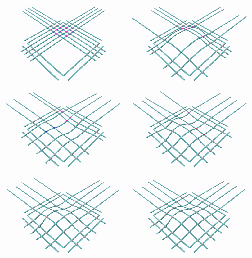
Simulation of the reconfigureable surface display Simulation of the reconfigureable surface display executed by collaborator, Sofia Wyetzner


Summary

DuneDisplay is a robotic system that displays continuous surface approximations using a grid of flexible, elastic racks and an array of actuators. While continuous surfaces are often seen in design, they are difficult to dynamically display in the physical world. By imposing kinematic constraints and actuation via many independently functional modules, we can control the output geometry of the flexible rack grid. The goal is to go from a target surface to a simulated stable state, then to a physical approximation on the DuneDisplay.

The display is currently in the process of being designed and constructed.

System Description

When built, DuneDisplay will consist of 24 individually moving devices that communicate with each other via RF. The devices fall into three categories: (1) brake nodes that are located at each intersection of two flexible racks, (2) end nodes located at one end of a single flexible rack, and (3) extrusion nodes located on the opposite end of a flexible rack from an end node. During shape display, the amount of rack in each display is controlled by the extrusion nodes. The location of each grid intersection is controlled through a combination of translation, extrusion, and opening or closing of the brake nodes. As a multi-stable system, it also requires biasing mechanisms at the ends of the rack. DuneDisplay is underactuated and multi-stable, so the final configuration depends in large part on the order of operations.

Example rendering on 1-by-1

Consider this example rendering on a 1-by-1 version of the DuneDisplay. If extruding directly between two points, the rack has two stable states: one that bends up and one that bends down. In order to achieving the sinusoidal target shape in the correct orientation

  1. The system starts at flat
  2. A small amount is extruded in to allow some slack while the end biases in the desired direction
  3. Extrusion continues until the desired length to one side of a brake node is achieved
  4. The crossing rack’s nodes translate until the brake intersection is at the desired location
  5. Then the extrusion node biases downward

Brake Nodes

Braking node has a brake corresponding to each direction in the flexible rack grid

End Nodes

End nodes contain biasing and translating subsystems

Extrusion Nodes

Extrusion nodes have an additional motor for extruding the rack into the system

Current State of the Project

Each of the three categories of node has a working prototype. Integration into the larger system is now underway.

Return to work